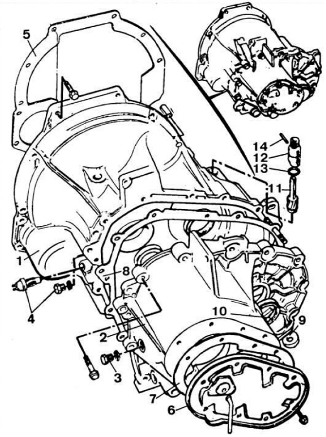
 Pic. 3.6. Parts of the gearbox housing.
1 - clutch housing; 2 - gearbox housing; 3 - stopper of the control hole; 4 - plug or reverse light switch; 5 - gasket; 6 - back cover; 7 - cover gasket; 8 - gasket between crankcases; 9 - magnetic washer; 10 - stuffing box; 11 - speedometer drive gear; 12 - speedometer drive housing; 13 - sealing washer; 14 - pin.
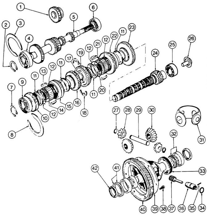
Input shaft 5 (pic. 3.7) made in the form of a block of drive gears, which are in constant engagement with the driven gears of all forward gears mounted on needle bearings on the output shaft 24.
 Pic. 3.7. Details of the four-speed gearbox and final drive.
1 - intermediate reverse gear; 2, 7, 13, 17, 20, 27 - retaining rings; 3, 8 - adjusting rings; 4 - input shaft bearing (larger diameter); 5 - input shaft; 6 - input shaft bearing (smaller diameter); 9 - ball bearing; 10 - driven gear of the fourth gear of the secondary shaft; 11 — a blocking ring of the synchronizer of III and IV transfers; 12 - synchronizer spring; 14 — a nave of the synchronizer of III and IV transfers; 15 - sliding clutch of the synchronizer of III and IV gears; 16 - driven gear III gear; 18 - persistent half rings; 19 - driven gear II gear; 21 - synchronizer hub I and II gears; 22 - blocking ring of the synchronizer of I and II gears with reverse gear; 23 - driven gear 1st gear; 24 - output shaft; 25 - bearing; 26 - oil slinger; 28 - satellite; 29 - the axis of the satellites; 30 - side gear; 31 — supporting clip satellites; 32 - tapered roller bearing; 33 - drive gear of the speedometer drive; 34 - sealing ring; 35 - pin; 36 - speedometer drive; 37 - driven gear of the speedometer drive; 38 - bolt; 39 - differential box; 40 - driven gear of the main gear; 41 - spring washer; 42 - gland.
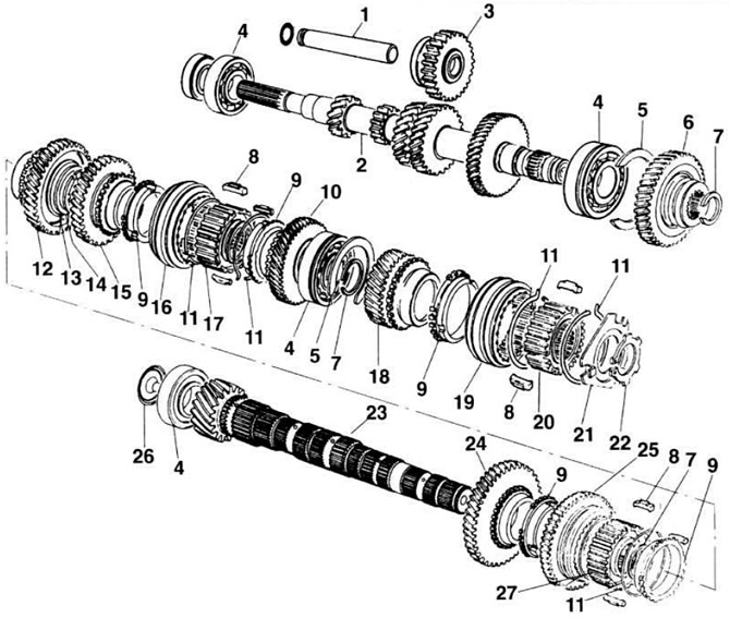
 Pic. 3.8. Details of a five-speed gearbox.
1 - axis of the intermediate reverse gear: 2 - input shaft; 3 — an intermediate gear wheel of a backing; 4 - shaft support bearing; 6 - adjusting ring; 6 - drive gear V transmission; 7 - retaining ring; 8 - cracker synchronizer; 9 — a blocking ring of the synchronizer; 10 - driven gear IV gear; 11 - synchronizer spring ring; 12 - driven gear II gear; 13 - thrust ring; 14 - retaining ring; 15 - driven gear III gear; 16 - synchronizer clutch III and IV gears; 17 - synchronizer hub III and IV gears; 18 - driven gear V transmission; 19 - clutch synchronizer V transmission; 20 — a nave of the synchronizer of V transfer; 21 - guide crackers of the synchronizer of the V transmission; 22 - lock washer; 23 - output shaft; 24 - driven gear 1st gear; 25 - synchronizer clutch of I and II gears with reverse gear; 26 - oil deflector; 27 - synchronizer hub of I and II gears.
Together with the secondary shaft, the main gear drive gear was made. The position of the shafts in the crankcase is fixed by adjusting rings 3 and 8. The thickness of which has three sizes: 1.86-1.89 mm; 1.94-1.97 mm; 2.01-2.04 mm. Double satellite differential. The driven gear 40 of the main gear is fixed on the differential box 39. The gearbox control drive consists of a gear lever, a ball joint, a drive rod, an intermediate shaft, a gear selection rod and a gear selection and shift mechanism.
In the five-speed gearbox, the input and output shafts are lengthened by about 50 mm, so the engine mounts and the right side member are also changed. The engine is offset to the right by 17 mm, and the spar is bent outward against the crankshaft pulley. The front wheel drive shafts have a different length.
The speedometer drive gear has 21 teeth. 4-speed driven gear - 20 with 145 SR 13 tires, 21 - with other tire sizes, five-speed type «TO» - 20 with 145 SR 13 tires, 19 with 155 SR13, 175/70 SR12, 185/60 HR 14 tires table 1.8.
Visitor comments