| Type | Single plate dry clutch |
| Drive unit | Hydraulic |
| Outside diameter | 210 mm |
| Pedal travel (unregulated) | 133±3mm |
Torque specification
| Name | Nm | lb-ft | lb-in |
| Clutch pressure plate to flywheel | 29 | 21 | - |
| Nipple for removing air from the hydraulic clutch | 10 | - | 89 |
Clutch elements
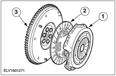
| Pos. | Spare Part No | Name |
| 1 | Clutch pressure plate | |
| 2 | Slave (friction) clutch disc | |
| 3 | Flywheel |
The clutch transfers torque from the engine to the gearbox. Clutch includes driven (friction) disc and pressure plate, which is bolted to the flywheel.
With the clutch engaged (depressed clutch pedal) power flow between engine and gearbox is interrupted. This means that when the clutch is not engaged, it is in the engaged (not free) condition. After depressing the pedal (engagement) clutch disengages (turns off).
Clutch driven and pressure plates
Special tool
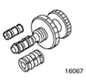 | Clutch Drive Alignment Tool 308204 (16-067) |
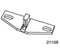 | Crankshaft locking tool 303393 (21-168) |
Withdrawal
1. Remove the gearbox. See Section 308-03A / 308-03B / 308-03C for more information.
2.
CAUTION: When reusing the clutch pressure plate, tighten the bolts evenly, in stages, in a criss-cross pattern, until the diaphragm spring is compressed (about two turns).
Disconnect the clutch from the flywheel. Turn out bolts and remove a pressure disk and a conducted disk of coupling from directing pins.
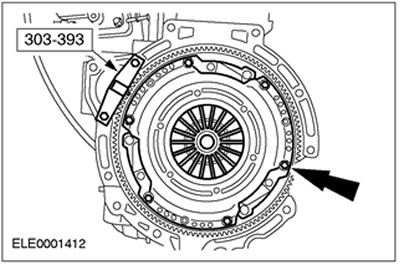
Installation
1. Center the clutch disc on the clutch pressure plate.
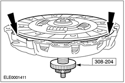
2.
CAUTION: Tighten the bolts evenly, in stages, in a criss-cross pattern, until the pressure plate is pressed against the flywheel.
Establish a conducted disk together with a pressure disk.
1. Using the special tool, install the pressure plate with the driven plate centered on it onto the flywheel guide pins.
2. Tighten the clutch pressure plate bolts in a crosswise manner (six bolts). Remove the alignment tool.
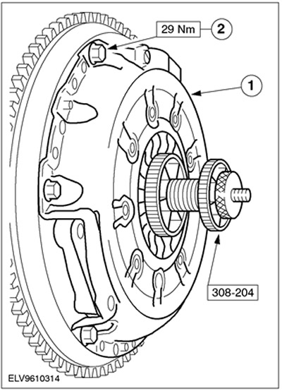
3. Install the gearbox. See Section 308-03A / 308-03B / 308-03C for more information.
Visitor comments