If the valve seats are badly worn or burst, new valve seat rings can be inserted, and the cylinder head must be drilled to the appropriate dimensions. The valve seats must always be run in concentrically with the valve guides.
valves
Check valve stems for excessive wear, gouges or cracks. Place a steel ruler along the well-cleaned valve stems and check that the stems are straight. Deformations are not allowed, otherwise the rods may jam in the guides. Check the valve discs for scale or cracks. Distance between the upper surface of the valve and its upper edge (valve edge width) must be at least 0.8 mm.
Valve guides

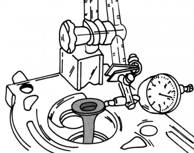
Pic. 74. Checking clearance between valve stem and valve guide
Guide bushings are integrated into the cylinder head. If the gap between the valve stem and the guide sleeve is too large, the valve guides must be turned. Check the clearance first. To do this, insert the valve as shown in fig. 74 into the cylinder head and move it up and down. If the clearance seems too large, countersink the guides to use valves with larger stems. It is generally assumed that the gap should not exceed 0.50 mm for intake valves and 0.60 mm for exhaust valves.
Valves are available with two large repair stem sizes. Always countersink the valve guides from the valve head side. The size of the reamer depends on the degree of wear. The smallest reamer should be used first and then the smallest repair valve should be tried to determine if the gap is within the specified values.
Valve seats must be ground with a cutter after the guides have been reamed in order to maintain straightness between the guide and the seat.
Valve springs
It is better to replace the valve springs with new ones if the engine has significant mileage. The springs can be tested by placing the old and new springs end to end over a long screw and screwing a nut onto the screw (with matching washers). Tighten the nut so that the springs are under pressure and measure the length of the springs. If the used spring is 10% shorter than the new one, replace the whole set. Install the valve springs with the closed end pointing down.
cylinder head
Check the cylinder head for cracks or other defects. Check the mating surface of the cylinder head for deformation by placing a ruler lengthwise, across and diagonally across a well-cleaned surface and measuring the clearance with a feeler gauge. If the clearance is more than 0.15 mm, grind the surface of the cylinder head. Care must be taken not to remove too much metal during grinding. The maximum removal for grinding is indicated in the appendix.
Measure the holes for the camshaft bearings. The bearing diameters must be measured together with the camshaft journal diameters to determine the bearing play.
Visitor comments