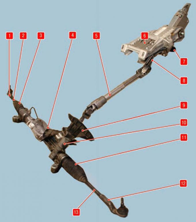
Pic. 8.1. Steering: 1 – a tip of the right steering draft; 2 – right steering draft; 3, 11 - protective covers; 4 - thermal screen; 5 - intermediate shaft; 6 – steering column; 7 – the lever of blocking of provision of a steering column; 8 – a shaft of a steering column; 9 - sealing case; 10 – steering mechanism; 12 – a tip of the left steering draft; 13 - left tie rod.
Steering is installed on Ford Mondeo cars (pic. 8.1) with a rack and pinion type steering mechanism equipped with a hydraulic booster and a safety steering column, adjustable in tilt and reach. The steering drive consists of two steering rods connected by ball joints to the steering knuckle levers of the front suspension.
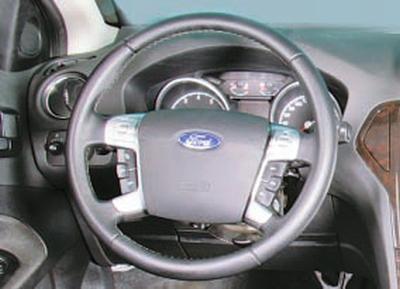
Steering wheel with driver's airbag, a horn switch is installed in the central steering wheel trim. The steering wheel hub is bolted to the steering column shaft.
The steering mechanism 10 is installed in the engine compartment and bolted to the front suspension subframe.
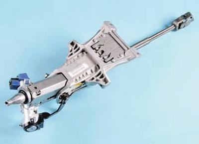
The steering column 6 is safety, with a mechanism for adjusting the position of the steering wheel, equipped with energy-absorbing devices that increase passive safety, and an anti-theft device in the ignition lock that blocks the steering wheel shaft from turning. The steering column also houses the controls for the headlights, turn signal, washer and windshield wiper.
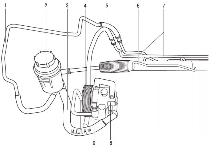
Pic. 8.2. Power steering system: 1 - drain line; 2 – a reservoir of system of the hydraulic booster of a steering with a working liquid; 3 - supply line; 4 – a pulley of the pump of the hydraulic booster of a steering; 5 - pressure line; 6 – steering mechanism; 7 – connecting tubes on the steering mechanism; 8 - power steering pump; 9 - pressure switch in the power steering system.
On fig. 8.2 shows the device of the power steering system of a car with a Duratec-HE engine with a working volume of 2.0 liters. The systems of cars with other engines are almost the same, the only difference is in the mutual arrangement of parts on the car.
The pressure of the working fluid in the hydraulic booster is created by a mechanical pump 8 of the vane type, which is installed on the engine and through the pulley 4 is driven by a V-ribbed belt common with the generator. The bypass valve installed in the pump maintains the required pressure of the working fluid in the power steering, depending on the engine speed.
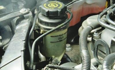
The power steering reservoir 2 is installed in the engine compartment on a bracket attached to the right of the radiator frame, and connected by a hose 3 to the power steering pump 8 and to the working fluid return line 1. If the power steering fails, the ability to drive the car is preserved, but the effort on the steering wheel increases.
Tie rods 2 and 13 (see fig. 8.1) attached to the steering rack with 6 ball joints. Tie rod ends 1 and 12 are attached to the steering knuckles of the front suspension using ball joints. From turning on the steering rods, the tips are fixed with locknuts. By rotating the steering rod in the ball joint relative to the tip, the toe-in of the front wheels is adjusted.
Visitor comments