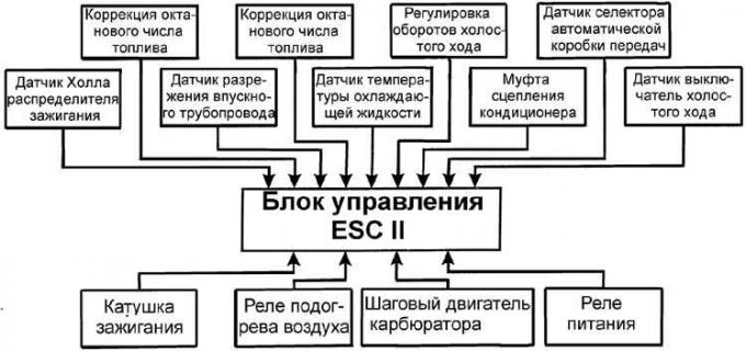
Block diagram of the ESC II control system

The ESC II carburetor and ignition control system includes an electronic control unit, an ignition coil, an ignition distributor with an integrated engine speed sensor, spark plugs and sensors for coolant temperature, intake manifold vacuum and the neutral position of the automatic transmission selector lever.
The ESC II electronic control unit controls the fuel and ignition systems at the same time, which contributes to obtaining maximum power and economy of operation throughout the entire engine load range.
The electronic control unit of the ESC II system receives signals from the sensors and, based on the information received, the unit controls the supply of voltage to the primary winding of the ignition coil and current interruption, and depending on the ignition timing, which is determined on the basis of information from the sensors, it supplies a high voltage pulse through the distributor to the corresponding spark plug and ignites the fuel mixture in the cylinder. Depending on the information received from the sensors, there is a constant change in the time intervals for supplying and turning off the current from the primary winding of the ignition coil, as a result of which the ignition timing is changed relative to the initial ignition setting angle. Also, based on the signal from the control unit, the intake manifold is heated and the engine idle speed is controlled.
All work related to checking the operation of the components of the ESC II system must be carried out on special equipment at a service station.
If there is an error in any of the data received from the sensor, the ESC II system enters standby mode. In this case, the ESC II system ignores the incorrect sensor signal, and assumes a pre-programmed value that will allow the engine to continue running (albeit with less efficiency).
Visitor comments