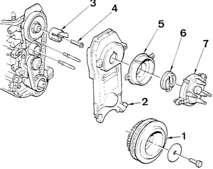
Elements of the ignition system of the CVH engine 1.8 dm sq. type R2A

1 - crankshaft V-belt pulley with toothed rim, 2 - crankshaft position and speed sensor, 3 - ignition distributor drive, 4 - drive mounting bolt, 5 - ignition distributor bracket, 6 - distributor rotor, 7 - distributor cover
Operating principle
The ESC electronic ignition control module receives signals from the position and speed sensor, coolant temperature sensor, intake air temperature sensor, and intake manifold vacuum sensor.
Based on these signals, as well as a memory map of the optimal ignition timing under various engine operating conditions, the ESC microprocessor module controls the current in the primary winding of the ignition coil, determining the moment of current interruption in the primary winding of the coil, depending on the signals received. High voltage current is supplied through the ignition distributor to the spark plug wires.
Then the module turns on the current in the primary winding for a strictly defined period of time and the process is repeated again, and the ignition timing is changed by the module depending on the information received.
The ESC ignition control module performs the following functions:
- determines the number of engine revolutions depending on the time interval that passes between successive pulses generated by the teeth of the crown moving in front of the position and speed sensor (double cut) between the teeth of the crown determines the position of the crankshaft 45°before TDC);
- determines the vacuum in the intake manifold, indicating the degree of engine load;
- on the basis of the information received and the data contained in the memory, determines the optimal ignition timing under given operating conditions;
- switches the current in the primary winding of the ignition coil on and off, causing a high voltage to be generated, which creates an ignition spark.
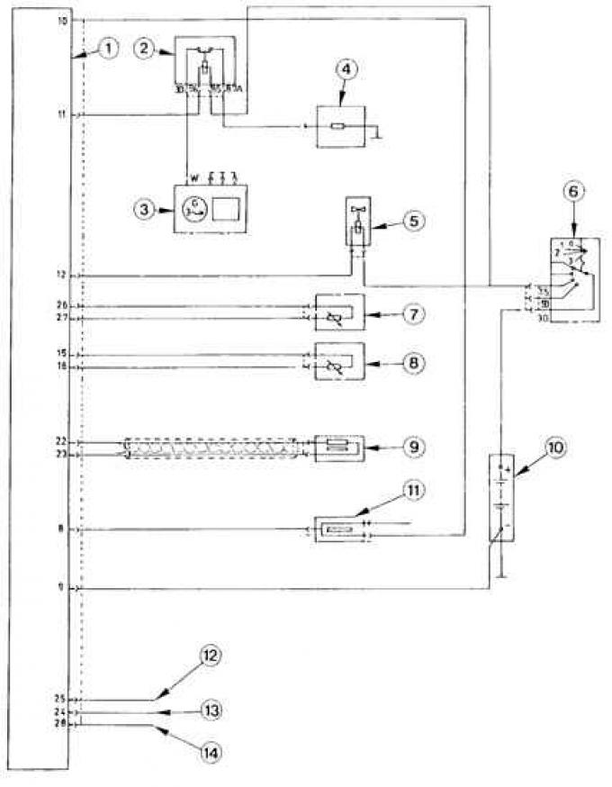
Electric circuit of the electronic control circuit of the ignition system type ESC

1 - ESC module, 2 - starter relay, 3 - alternator, 4 - starter, 5 - throttle lever damper solenoid valve (dash-pot), 6 - ignition switch, 7 - coolant temperature sensor, 8 - intake air temperature sensor, 9 - crankshaft position and speed sensor, 10 - battery, 11 - ignition coil, 12.13 - fuel octane corrector wire connectors, 14 - diagnostic connector
The ESC module also controls the engine, which actuates the carburetor throttle in the idle range, correcting its position depending on the load (automatic transmission on, air conditioning on) and thermal state of the engine.
Checking the ignition system
The ignition system does not require adjustment. Removal and installation of the ignition distributor is not difficult (see fig. Elements of the ignition system of the CVH engine 1.8 dm sq. type R2A), especially since it can only be installed in one, correct position.
The ignition distributor is checked with a multimeter. The test method is given in the table concerning the test of the ignition system.
ESC ignition system test method
| Checked element | Measurement between contacts | Meaning | Remarks |
| Crankcase ground connection | "9" and weight "10" and weight | 0 - 0.5 ohm | Ignition off |
| Starter relay | "11" and mass | 12 - 14 V | Ignition on |
| Throttle lever damper solenoid valve (dash-pot) | "12" and weight | 12 - 14 V | Ignition on |
| coolant temperature sensor | "26" and "27" | – | Ignition off |
| Intake air temperature sensor | "15" and "26" | – | Ignition off |
| Crankshaft position and speed sensor | "22" and "23" | – | Ignition off |
| Power supply of the primary winding of the ignition coil | "8" and "9" | 12 - 14 V | Ignition on |
| Fuel octane corrector | "25" and "9" "24" and "9" | The resistance is infinite | Disconnect the ESC module before testing; ignition on |
Visitor comments