Body sedan
1. Raise the rear of the vehicle.
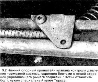
2. Remove the valve bracket from the lower suspension control arm (see picture).
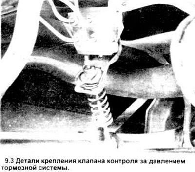
3. Mark the position of the four hydraulic lines on the valve (see picture) unscrew the nuts from the pipe, if possible using a box wrench. Carefully disconnect the tubing from the valve.
4. Unscrew the two bolts securing the valve to the head pan, then disconnect the valve from the vehicle.
Installation
5. With the valve on the floor tray, screw in the two mounting bolts and tighten them securely.
6. Connect the valve bracket to the lower control arm, install the retaining bolt and tighten it securely.
7. Insert the brake pipes into the valve. Thread the nuts onto the pipe, being careful not to cut them off, then tighten securely, preferably with a ring wrench.
Adjustment
9. Lower the vehicle and rock it several times to bring the suspension into normal working condition.
10. Cut a piece of hose or tube 16.3 mm long with an inside diameter of 6.35 mm. (1/4 inch) and make a slit in it on the side (see picture).
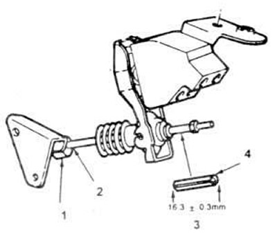
9.10. The brake pressure control valve is adjusted by inserting a piece of rubber or plastic tubing between the top control rod nut and the arm, then moving the adjusting sleeve so that it fits into the pocket of the bottom support bracket (the vehicle must be at normal height when performing this operation).
1. Valve bolt.
2. Set adjusting bolt.
3. Cut the tube to that length.
4. Adjusting sleeve.
11. Moving along the bottom of the rear of the car, lower the valve adjusting screw (see picture).
12. Using a piece of pipe as an intermediate ring, install it on the upper end of the working rod. If necessary, move the adjusting sleeve up or down until it rests on the support bracket pocket on the lower control arm. Tighten the adjusting sleeve set screw securely.
Station wagon
13. Place a rag under the master cylinder and prepare caps or plastic plugs to cover the ends of the tubes after they have been disconnected.
14. Loosen the tube nut (main or secondary, depending on which valve will be removed), at the point where it enters the pressure control valve, using a ring wrench if possible.
15. Unscrew the pressure control valve from the master cylinder (see picture). Close the opening in the master cylinder to avoid excessive fluid loss and contamination.
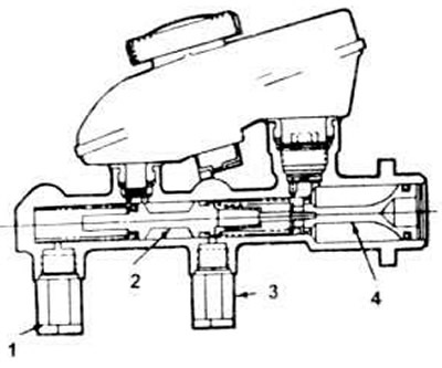
9.15. In body type "station wagon" The brake pressure control valves are screwed into the brake master cylinder.
1. Right rear pressure control valve.
2. Secondary piston.
3. Left rear pressure control valve.
4. Block of the main piston.
16. Installation is carried out in the reverse order. Be sure to bleed the brakes as instructed in section 11.
Visitor comments